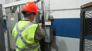
 Arc Flash An arc flash is a sudden, intense release of electrical energy caused by a fault or short circuit in an electrical system. This release generates an explosive burst of light and heat, capable of causing severe burns, injuries, and damage to equipment within the vicinity of the fault. arc flash analysis
Arc Flash Analysis An arc flash analysis is an engineering study that is initiated to calculate the potential incident energy (measured in Calories Per Centimeters Squared or Cal/Cm2) and the Flash Protection Boundary of an arc flash.
Coordination Study An additional engineering study added on to the arc flash analysis that assesses the trip sequence of each fuse and circuit breaker (breaker) in relation to one another with the sole objective of protecting equipment and ensuring uptime reliability. This is done by comparing Time Current Curves (TCC) or sometimes refers to as Time Trip Curves (TTC) of the protective devices (fuses and/or breakers). The engineer will make recommendations such as alternate breaker settings or fuse types to minimize downtime and damage if a fault were to occur. Such studies are typically conducted in larger facilities demanding a heightened level of reliability, like hospitals, data centers, or corporate headquarters. No additional field data collection will be required.
Mitigation Study Similar to a Coordination Study, a Mitigation Study utilizes the same engineering steps. However, the intention is to reduce the arc flash hazard levels (usually to reduce high incident energy down to 12 Cal/Cm2 or lower with a goal to reach below 1.2 Cal/Cm2 where possible) by making recommendations of alternate breaker setting or fuse types. This may not always be possible with the existing electrical equipment or economically feasible due to fixed trip devices or costly replacement with new devices. A Mitigation Study ultimately puts Life Safety over Equipment Reliability for the engineer to consider and recommend a responsible balance.
Important Questions for Quoting any Arc Flash Project
Who is your point of contact?
Facility Manager or Facility Engineer will often require a more in-depth scope of work that may include a Coordination or Mitigation Study.
HS & E or EH & S Manager In some cases has little or no background experience with the arc flash study process and looking to “just have labels installed”. After the arc flash analysis is completed and the incident energy levels are established, recommendations can then be made if mitigation is possible and effective. This will be an additional sale to the client and will require the engineer to provide a quote to the Contractor.
About half of the time your customer will have a written scope of work that they what you to provide a quote based on. They probably got this scope by Googling “Arc Flash Scope of Work” and downloaded a very complicated and expensive “to-do list” of requirements. I always try to talk them down to a more reasonable scope by asking them what the most important aspects of the scope are and then pointing out where a cost savings could occur.
A Basic Arc Flash Analysis will include:
- Data Collection
- Engineering Evaluation, Interpretation and Analysis
- Arc Flash Electrical One-Line (Required)
- Short Circuit Analysis (Required)
- Device Evaluation (Required)
- Coordination /Mitigation (optional)
- Engineering Recommendations (Report cover letter)
- Label Installation (Optional)
- Electrical Safety Training (Optional, can be done at anytime during the arc flash analysis)
If the client does not have a written scope, these questions will help to define the scope of work:
- Do you have a “One-Line” or sometimes referred to as a “Single-Line Diagram”? A “point count” or “Bus Count” can be calculated from those.
- Have you done an arc flash study in the past? Do you have the old report? The old report will have a complete list of each bus documented.
2B. Do you have or own the SKM PowerTools or Easy Power software data files? These are the software programs that are used 99% of the time and will have the complete bus count. If they do have these files, the scope will revolve around what was changed or has been added.
- Can you do a walk-thru? If possible, you will walk the facility or facilities and count all 3-phase electrical distribution, then the 3-phase production control panels. Keep these two totals separate from one another for quoting options. The options will be a quote just for the Power Distribution Equipment and a second line item for the 3-phase production control panels. This strategy will allow the client to break the project into phases if capital is an issue.
- Do you have any historical electrical maintenance reports (Infrared Thermography [IR] Study)? Typical IR Reports will contain the 3-phase power distribution equipment, not often will you find production control panels.
- Can the client provide an estimated label count? This will have to start with the facilities Power Distribution. An arc flash analysis must begin with where the Utility Company comes into the building. Ask for a separate count of 3-phase production control panels. This is done to provide quoting options.
- Is there an up-to-date floor plan? Some floor plans will include the facilities, power distribution equipment as well as the production control panels.
- You have an up-to-date Asset List? Some asset lists will include the facilities, power distribution equipment as well as the production control panels.
- How many Utility or Primary Transformers are feeding the facility and what are the sizes (measured in kVA [Kilovolt Amps])? Worst case scenario, you can make a judgment call of the bus count based on the transformer size(s). Typically, a 2,500 kVA transformer will have 65-85 power distribution loads for each transformer.
Data Collection Data collection refers to the field work portion of the arc flash analysis process. It involves locating and cataloging electrical attributes while the equipment is energized and their relationships to one another.
Engineering Evaluation, Interpretation and Analysis The Licensed Engineer of Record will interpret and analyze the collected data by building an electrical model in a software program such as SKM PowerTools or Easy Power called an Arc Flash Electrical One-Line.
The next step is a review the Arc Flash Electrical One-Line for:
- Data Collection Technician will review the arc flash one-line diagram for accuracy.
- Client representatives review the one-line diagrams for correct nomenclature and accuracy. (According to the National Electrical Code, every electrical device is required to have its own unique name.)
Once the client has signed off on the engineering review the engineer will perform the necessary incident energy and arc flash protection boundary calculations. They will review each circuit to see if it meets the National Electric Code requirements. In my experience, approximately 90 percent of these code violations are due to protective devices being mismatched to the associated wire. Next the engineer runs the Short Circuit Analysis. This is done with the software model by mathematically imposing a fault at each protective device to calculate what the Maximum Short Circuit Current could be. That information will be used to compare the equipment’s Short Circuit Current Rating (SCCR) versus the Calculated Maximum Short Circuit Current. This is called the Device Evaluation, and the protective device will receive a Pass or Fail. If any Fail, the engineer will make a corrective recommendation that result in additional engineering outside of the original scope and a Change Order.
At this point the engineer has the opportunity to conduct a Mitigation or Coordination Study as described above if the client requires this level of service.
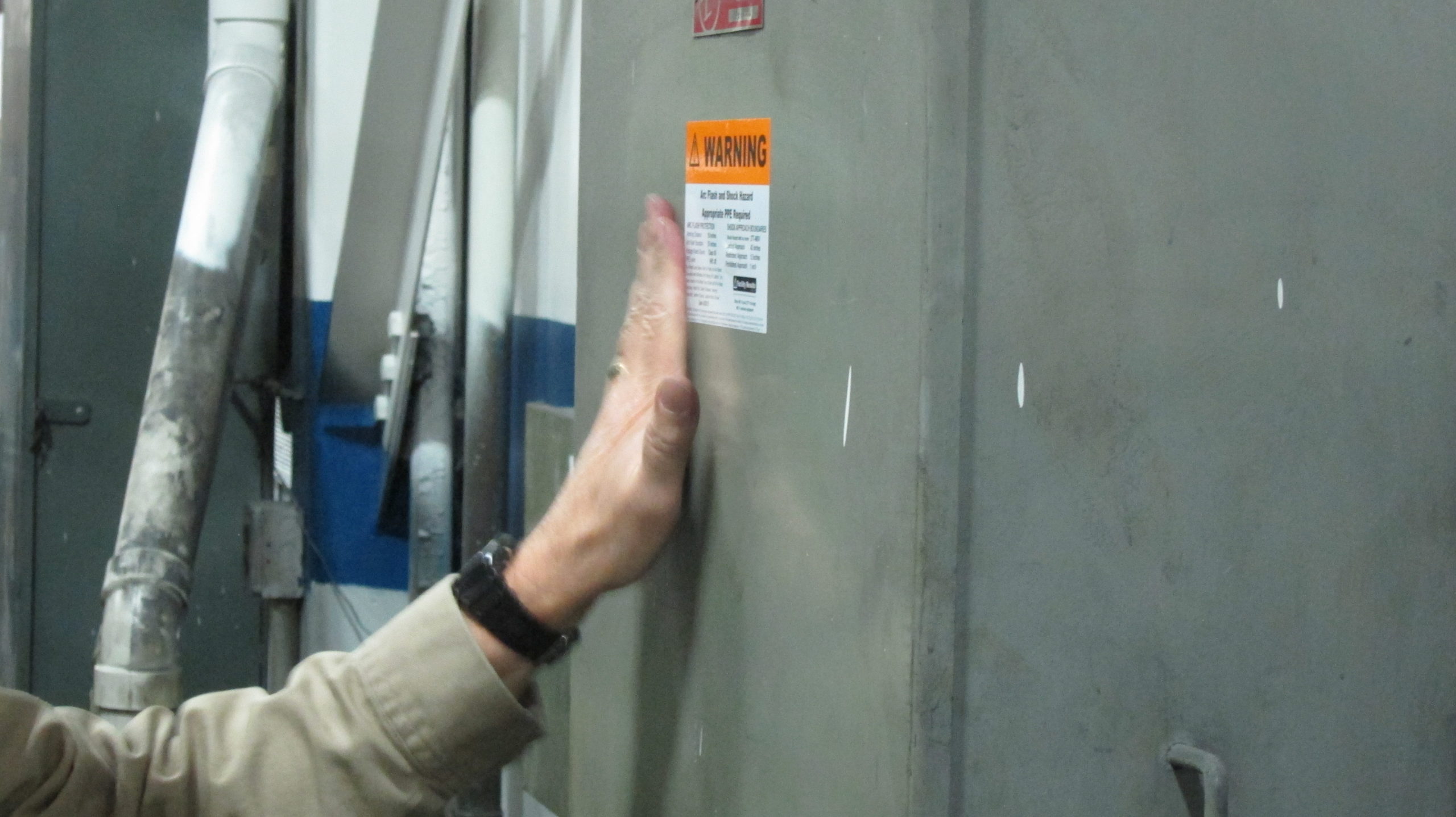
Label Installation This is the final step in the Arc Flash Analysis. This is an optional service that could be completed by the client or contractor. The label shall be placed on the equipment that matches the nomenclature on the Label. It is required to be placed in an area that can be easily seen by the Qualified Worker.
The minimum required information that shall be on the label is Nominal Voltage, Arc Flash Boundary, Date the label was produced or the date the label expires and one of the following: Incident Energy (Cal/Cm2), Personal Protective Equipment (PPE) Category or Site-Specific PPE Level.
The Label can also include as a best practice; Glove Voltage Class, List of the PPE requirements, Limited Approach Boundary, Restricted Approach Boundary, QR Code to the contractors website that should contain further detail and information on the PPE requirements, the contractor Logo and a disclaimer stating if the system is changed, or maintenance lapse the engineering findings are invalid.
The NFPA 70E requires all arc flash labels to be reviewed and updated in intervals not to exceed 5-years or if there has been any major modifications or changes.
Electrical Safety Training Can be done at any time during the analysis process. The training shall consist of awareness training of electrical hazards, PPE selection, PPE care, PPE inspection, how to read the arc flash label, how to evaluate equipment for its condition, and other best practices. This training should take Two hours for a refresher training if the Qualified Workers are familiar with the current NFPA 70E Standard or Four hours if they are new to the NFPA 70E Standard or it’s been Three or more years since their last electrical safety training as required by the NFPA 70E Standard.
The NFPA 70E requires training of the Qualified Worker not to exceed 3 years to account for changes in the Standard as it updated in 3-year increments.

